
Our Products
Browse our products and send an enquiry to purchase.
6 products found
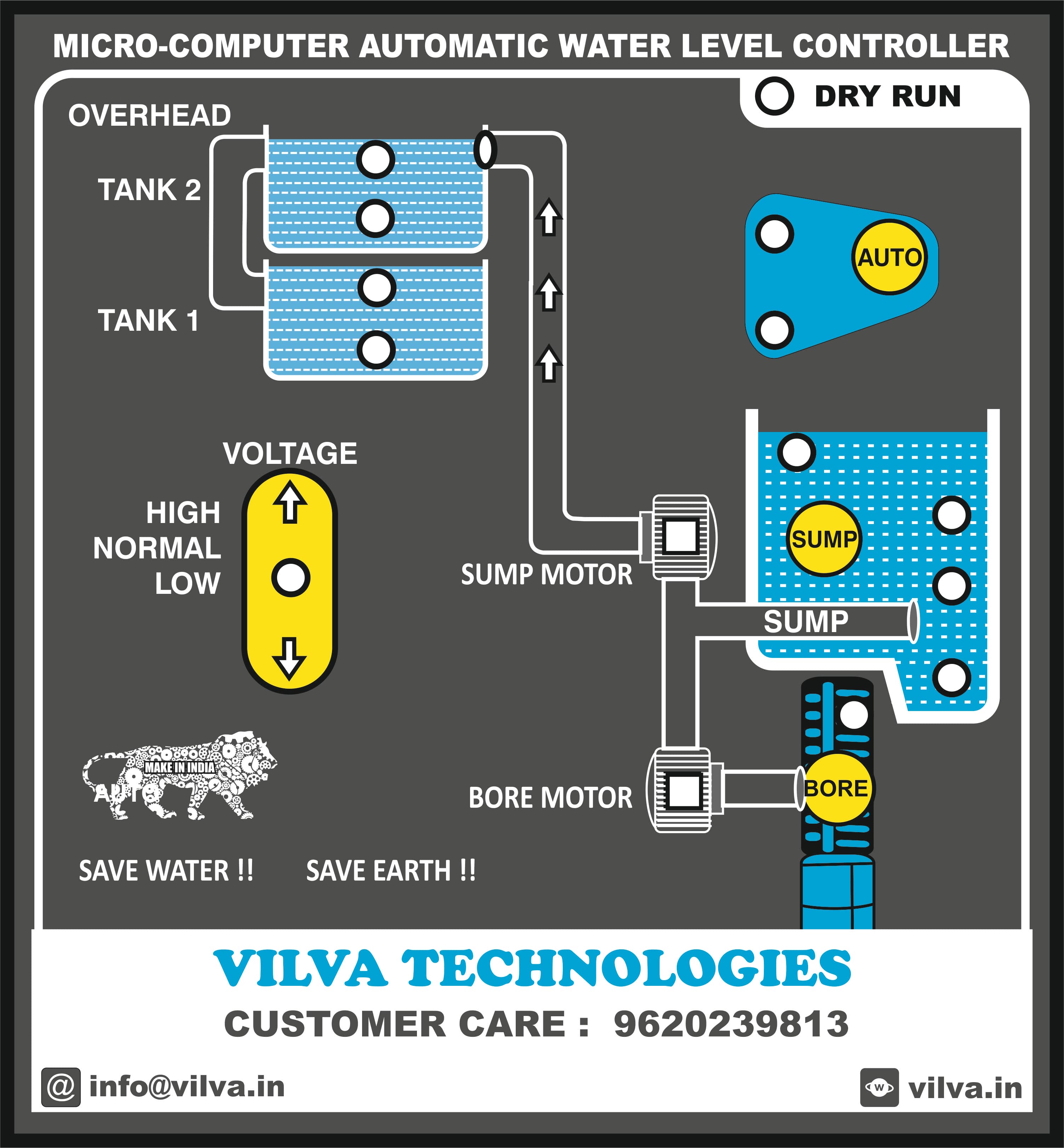
Water Management Control System: Features Overhead tank-1 level 50% and 100% Overhead tank-2 level 50% and 100% Sump tank level 25%, 50% and 100%. Water flow indications DRYRUN indication. Power supply indication Low/Hi voltage indication AUTO and MANUAL mode indications NEED option in auto mode SUMP or BORE selection in auto mode. Stainless steel bullet and flow guard sensors. Water Management Control System: Revised Functional Specification This document establishes the official operational logic, automation parameters, and safety protocols for a dual-source fluid management system utilizing both a Sump Motor and a Bore-well Motor. ________________________________________ 1. System Safeguards & Power States • Power Control: A master physical switch enables complete system power-up or absolute hardware shutdown. • Electrical Interlock: The system continuously samples incoming voltage. If a Low-Voltage or High-Voltage fault occurs, both the Sump Motor and the Bore-well Motor are strictly locked out from activating. ________________________________________ 2. Autonomous Mode Operations (AUTO) 2.1 Replenishment Cascading Logic When the Overhead (OH) Tank-1 or Tank-2 drops to < 50%, the system queries the Sump Tank to choose its source: Scenario A: Sump Source Available • Trigger: Sump Tank level is ≥ 25%. • Action: System activates the Sump Motor and illuminates the Motor ON indicator. • Flow Monitoring: If fluid entry to the OH Tank is not detected within a few minutes, the motor cuts power, and the system triggers a DRY RUN indication. • Termination: The Sump Motor turns OFF automatically when the OH Tank-1 and Tank-2 reaches 100%. Scenario B: Sump Source Dry (Bore-well Diversion) • Trigger: Sump Tank level is dry (< 25%). • Action: Sump Motor is locked out. System automatically activates the Bore-well Motor. • Flow Monitoring: The Bore-well must deliver water to either the Sump or the OH Tank. If flow fails to register within a few minutes, the Bore-well Motor turns OFF and triggers a DRY RUN indication. • Termination: The Bore-well Motor automatically turns OFF when either the Sump Tank or the OH Tank-1 and Tank-2 fills to 100%. 2.2 Sump Refill & Automatic Handoff • Sequential Switch: If the Bore-well is filling the Sump Tank and it reaches 100%, the Bore-well Motor immediately cuts power. • Handoff Action: The system instantly transitions to activate the Sump Motor to fill the OH Tank. • Handoff Monitoring: The system checks for OH Tank water flow. If missing after a few minutes, the Sump Motor shuts down and declares a DRY RUN event. • Final Cut-off: The Sump Motor stops when the OH Tank-1 and Tank-2 reaches 100%. ________________________________________ 3. Manual Overrides & System Failures 3.1 Semi-Automated Filling (NEED Routine) • Purpose: Manually force-start a replenishment cycle for either reservoir before reaching low automation limits. • Behavior: Activating this command turns ON the Sump or Bore-well motor based on current reservoir states. • Safety Resets: Motors automatically cut power once their targeted reservoir (Sump or OH Tank-1 and Tank-2) reaches 100%. 3.2 Manual Mode (Bypass Mode) • Purpose: Provides a redundant fallback in the event of controller or sensor failure. • Behavior: Bypasses the automation logic entirely, allowing operators to directly turn the Sump Motor and Bore-well Motor ON or OFF based on real-time operational requirements. ________________________________________
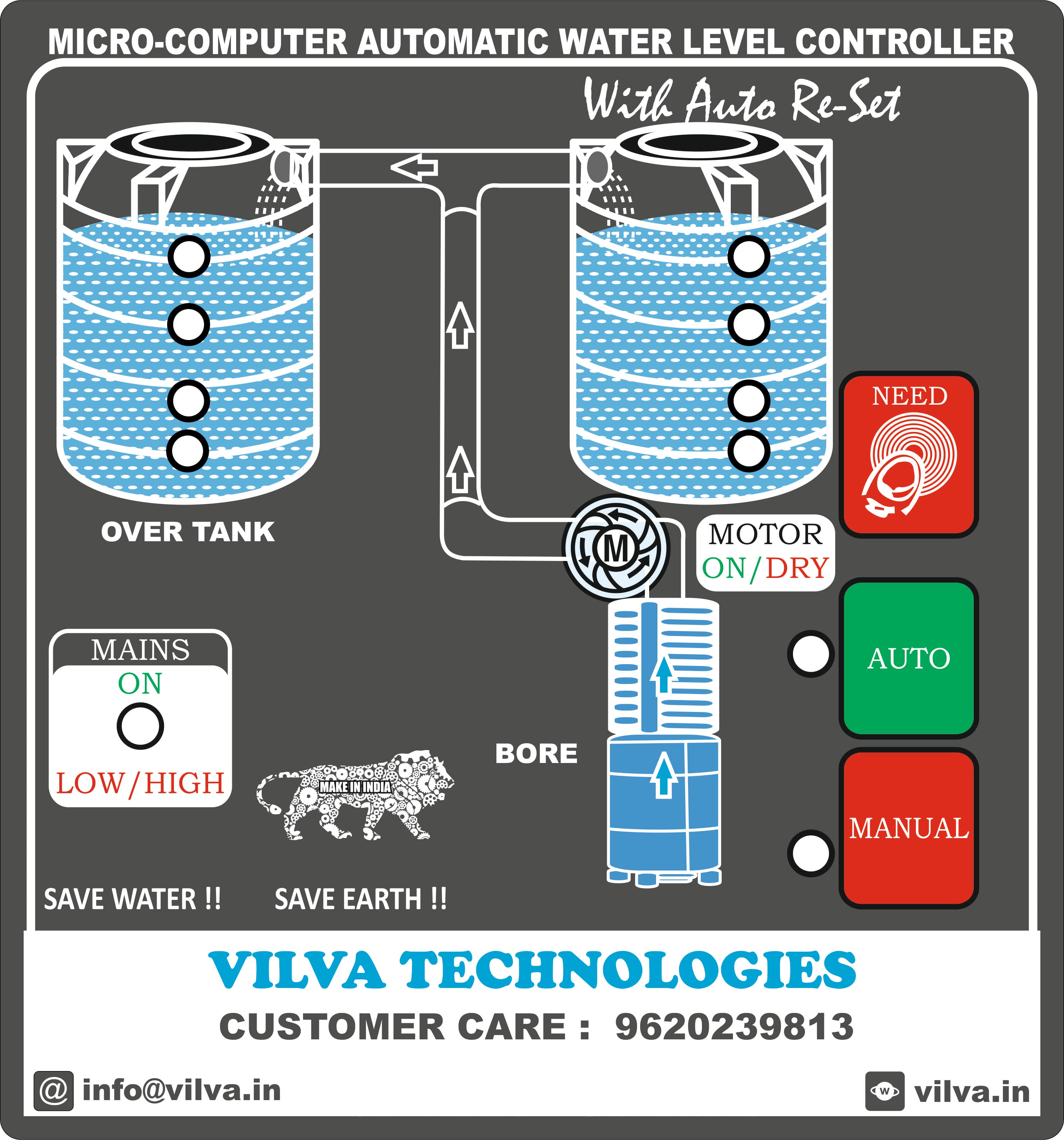
Water Management Control System: Features Overhead tank-1 level 50% and 100% Overhead tank-2 level 50% and 100% Water flow indications DRYRUN indication. Power supply indication Low/Hi voltage indication AUTO and MANUAL mode indications NEED option in auto mode Stainless steel bullet and flow guard sensors. Water Management Control System: Functional Specification This document establishes the official operational logic, automation parameters, and safety protocols for the embedded controller of the dual-tank fluid management system. ________________________________________ 1. Electrical Safety & Operational Safeguards • Voltage Monitoring: The microcontroller continuously samples the incoming voltage level. • Interlock Protocol: If the system detects a Low-Voltage or High-Voltage fault condition, the bore motor drive relay is strictly inhibited from initializing. • Fault Override: Voltage safety limits supersede all water-level demand cues. ________________________________________ 2. Autonomous Mode Operations (AUTO) 2.1 Replenishment Initiation Demand Threshold: Initiation sequence executes when the overhead tank-1 or overhead tank-2 level drops to < 50%. 2.2 Fluid Dynamics & Priming Diagnostics • Flow Detection Window: Upon motor activation, the system initiates a 3-minute priming countdown timer. • Positive Feedback Loop: If fluid flow is detected at the overhead tank inlet within 3 minutes, the Water Flow fascia indicator activates, and the pump maintains continuous operation. • Dry-Run Exception: If no fluid entry is registered within 3 minutes, the system cuts motor power, suppresses the flow indicator, and logs a DRYRUN fault state on the user interface. 2.3 Fault Recovery & Lockout Parameters • Transient Fault Reset: Upon an initial DRYRUN event, the controller enters a 1-hour cooling period. After 1 hour, the system executes an Auto-Reset routine and attempts replenishment. • Critical Lockout: If a DRYRUN event registers more than 2 consecutive times, the system transitions into a Permanent Fault State. • Manual Override Clearance: The Permanent Fault State completely disables the Auto-Reset routine. Normal system operations can only be restored via physical operator intervention by depressing the tactile NEED button. • Upper Limit Termination: When the both overhead tank-1 and overhead tank-2 reaches 100% capacity, the motor is deactivated to prevent reservoir overflow. ________________________________________ 3. Operator Interface Commands & Manual Overrides 3.1 Semi-Automated Filling (NEED Routine) • Purpose: Allows operators to initiate a top-up sequence prior to reaching the low-level automation threshold. • Execution: Activated by a brief touch of the NEED button on the interface panel. • Safety Resets: The routine follows identical safety loops and terminates automatically when the overhead tank hits 100% or if a DRYRUN condition is encountered. 3.2 Auxiliary Manual Bypass (MANUAL Mode) • Purpose: Facilitates auxiliary direct water usage (e.g., ground cleaning, landscaping) by diverting the discharge line. • Execution: Activated via the MANUAL selection button. • Bypass Profile: The system forces the bore motor into continuous operation and bypasses the 3-minute dry-run flow timer restriction. • Termination & Auto-Reversion: The system automatically terminates Manual Mode and directly reverts to standard AUTO operation if: o The overhead tank-1 and overhead tank-2 sensor registers 100% capacity (Overfill safety protocol). o The operator manually engages the AUTO button on the control console.
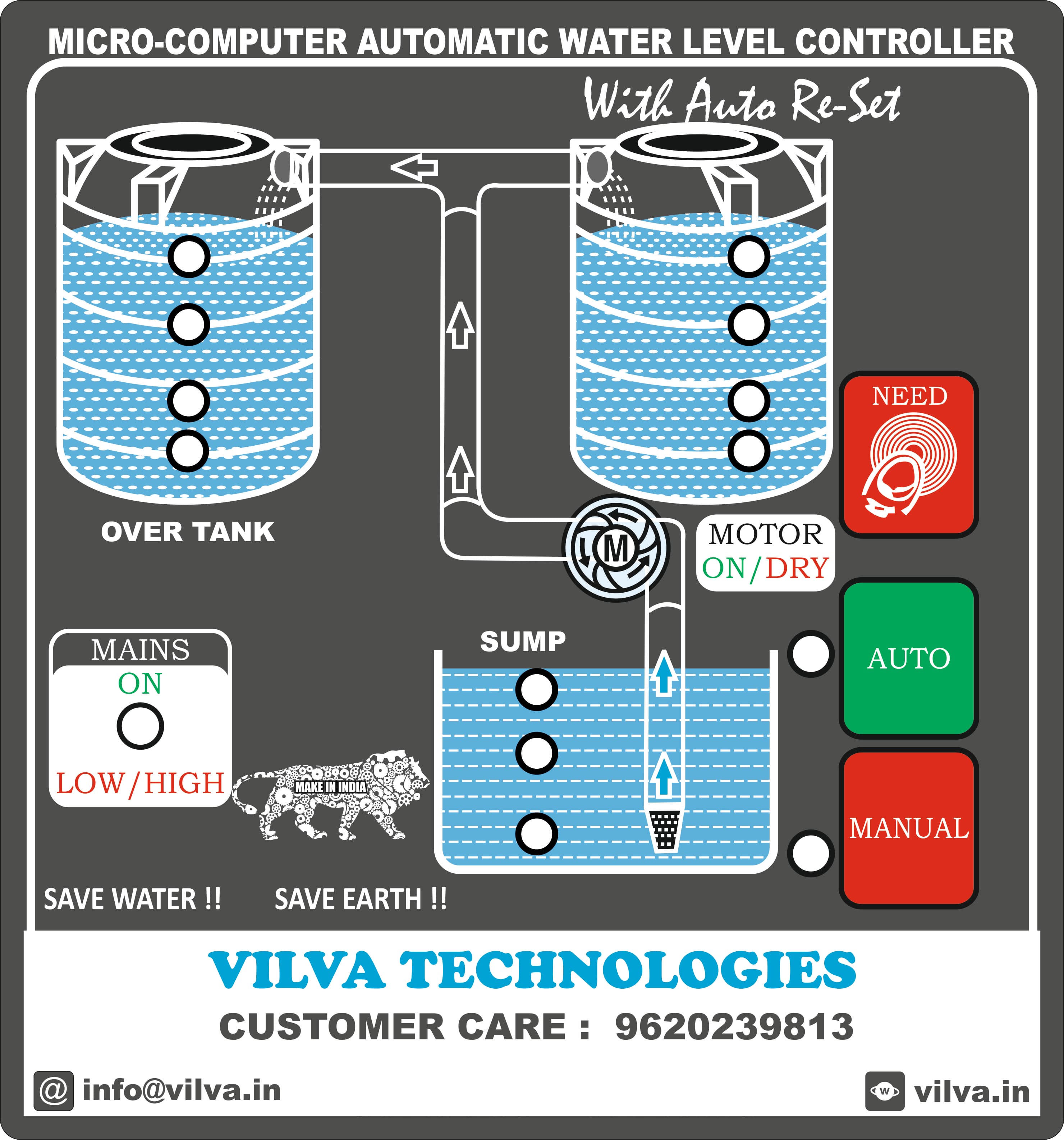
Water Management Control System: Features Overhead tank-1 level 50% and 100% Overhead tank-2 level 50% and 100% Sump tank level 25%, 50% and 100%. Water flow indications DRYRUN indication. Power supply indication Low/Hi voltage indication AUTO and MANUAL mode indications NEED option in auto mode SUMP or BORE selection in auto mode. Stainless steel bullet and flow guard sensors. Water Management Control System: Functional Specification This document establishes the official operational logic, automation parameters, and safety protocols for the embedded controller of the dual-tank fluid management system. ________________________________________ 1. Electrical Safety & Operational Safeguards • Voltage Monitoring: The microcontroller continuously samples the incoming voltage level. • Interlock Protocol: If the system detects a Low-Voltage or High-Voltage fault condition, the sump motor drive relay is strictly inhibited from initializing. • Fault Override: Voltage safety limits supersede all water-level demand cues. ________________________________________ 2. Autonomous Mode Operations (AUTO) 2.1 Replenishment Initiation • Demand Threshold: Initiation sequence executes when the overhead tank-1 or overhead tank-2 level drops to < 50%. • Source Verification: The system queries the sump tank level prior to motor engagement. • Engagement Window: If the sump reservoir level is ≥ 25%, the controller activates the sump motor relay and illuminates the Motor ON fascia indicator. 2.2 Fluid Dynamics & Priming Diagnostics • Flow Detection Window: Upon motor activation, the system initiates a 3-minute priming countdown timer. • Positive Feedback Loop: If fluid flow is detected at the overhead tank inlet within 3 minutes, the Water Flow fascia indicator activates, and the pump maintains continuous operation. • Dry-Run Exception: If no fluid entry is registered within 3 minutes, the system cuts motor power, suppresses the flow indicator, and logs a DRYRUN fault state on the user interface. 2.3 Fault Recovery & Lockout Parameters • Transient Fault Reset: Upon an initial DRYRUN event, the controller enters a 1-hour cooling period. After 1 hour, the system executes an Auto-Reset routine and attempts replenishment. • Critical Lockout: If a DRYRUN event registers more than 2 consecutive times, the system transitions into a Permanent Fault State. • Manual Override Clearance: The Permanent Fault State completely disables the Auto-Reset routine. Normal system operations can only be restored via physical operator intervention by depressing the tactile NEED button. 2.4 Resource Depletion & Recovery Thresholds • Low-Source Cut-off: If the source sump level drops below 25%, the motor is immediately deactivated to prevent mechanical damage. • Hysteresis Recovery: Following a low-source shutdown, the system ignores initial refills at 25% and enforces a buffer delay. Motor re-engagement is restricted until the sump volume recovers to a minimum threshold of 50%. • Upper Limit Termination: When the overhead tank reaches 100% capacity, the motor is deactivated to prevent reservoir overflow. ________________________________________ 3. Operator Interface Commands & Manual Overrides 3.1 Semi-Automated Filling (NEED Routine) • Purpose: Allows operators to initiate a top-up sequence prior to reaching the low-level automation threshold. • Execution: Activated by a brief touch of the NEED button on the interface panel. • Safety Resets: The routine follows identical safety loops and terminates automatically when the both overhead tank-1and overhead tank-2 hits 100% or if a DRYRUN condition is encountered. 3.2 Auxiliary Manual Bypass (MANUAL Mode) • Purpose: Facilitates auxiliary direct water usage (e.g., ground cleaning, landscaping) by diverting the discharge line. • Execution: Activated via the MANUAL selection button. • Bypass Profile: The system forces the sump motor into continuous operation and bypasses the 3-minute dry-run flow timer restriction. • Termination & Auto-Reversion: The system automatically terminates Manual Mode and directly reverts to standard AUTO operation if: o The overhead tank-1and overhead tank-2 sensor registers 100% capacity (Overfill safety protocol). o The operator manually engages the AUTO button on the control console.
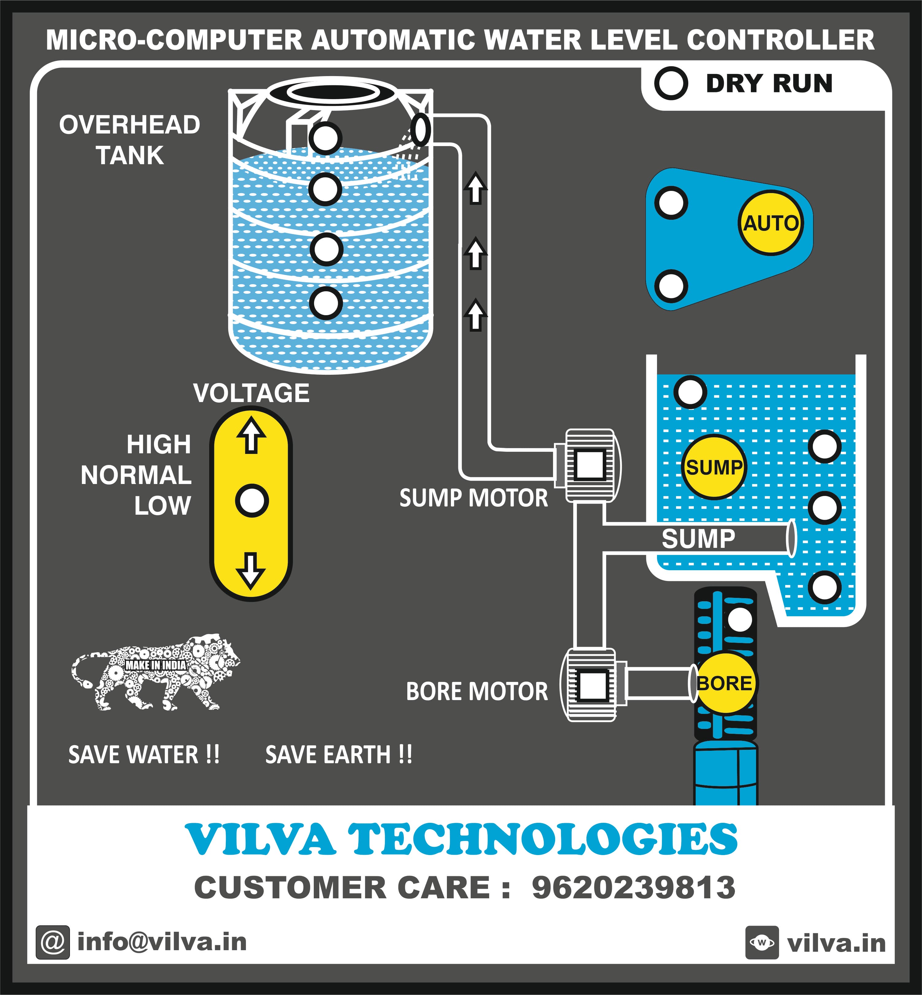
Water Management Control System: Features Overhead tank level 25%, 50% 75% and 100% Sump tank level 25%, 50% and 100%. Water flow indications DRYRUN indication. Power supply indication Low/Hi voltage indication AUTO and MANUAL mode indications NEED option in auto mode SUMP or BORE selection in auto mode. Stainless steel bullet and flow guard sensors. Water Management Control System: Revised Functional Specification This document establishes the official operational logic, automation parameters, and safety protocols for a dual-source fluid management system utilizing both a Sump Motor and a Bore-well Motor. ________________________________________ 1. System Safeguards & Power States • Power Control: A master physical switch enables complete system power-up or absolute hardware shutdown. • Electrical Interlock: The system continuously samples incoming voltage. If a Low-Voltage or High-Voltage fault occurs, both the Sump Motor and the Bore-well Motor are strictly locked out from activating. ________________________________________ 2. Autonomous Mode Operations (AUTO) 2.1 Replenishment Cascading Logic When the Overhead (OH) Tank drops to ≤ 25%, the system queries the Sump Tank to choose its source: Scenario A: Sump Source Available • Trigger: Sump Tank level is ≥ 25%. • Action: System activates the Sump Motor and illuminates the Motor ON indicator. • Flow Monitoring: If fluid entry to the OH Tank is not detected within a few minutes, the motor cuts power, and the system triggers a DRY RUN indication. • Termination: The Sump Motor turns OFF automatically when the OH Tank reaches 100%. Scenario B: Sump Source Dry (Bore-well Diversion) • Trigger: Sump Tank level is dry (< 25%). • Action: Sump Motor is locked out. System automatically activates the Bore-well Motor. • Flow Monitoring: The Bore-well must deliver water to either the Sump or the OH Tank. If flow fails to register within a few minutes, the Bore-well Motor turns OFF and triggers a DRY RUN indication. • Termination: The Bore-well Motor automatically turns OFF when either the Sump Tank or the OH Tank fills to 100%. 2.2 Sump Refill & Automatic Handoff • Sequential Switch: If the Bore-well is filling the Sump Tank and it reaches 100%, the Bore-well Motor immediately cuts power. • Handoff Action: The system instantly transitions to activate the Sump Motor to fill the OH Tank. • Handoff Monitoring: The system checks for OH Tank water flow. If missing after a few minutes, the Sump Motor shuts down and declares a DRY RUN event. • Final Cut-off: The Sump Motor stops when the OH Tank reaches 100%. ________________________________________ 3. Manual Overrides & System Failures 3.1 Semi-Automated Filling (NEED Routine) • Purpose: Manually force-start a replenishment cycle for either reservoir before reaching low automation limits. • Behavior: Activating this command turns ON the Sump or Bore-well motor based on current reservoir states. • Safety Resets: Motors automatically cut power once their targeted reservoir (Sump or OH Tank) reaches 100%. 3.2 Manual Mode (Bypass Mode) • Purpose: Provides a redundant fallback in the event of controller or sensor failure. • Behavior: Bypasses the automation logic entirely, allowing operators to directly turn the Sump Motor and Bore-well Motor ON or OFF based on real-time operational requirements. ________________________________________
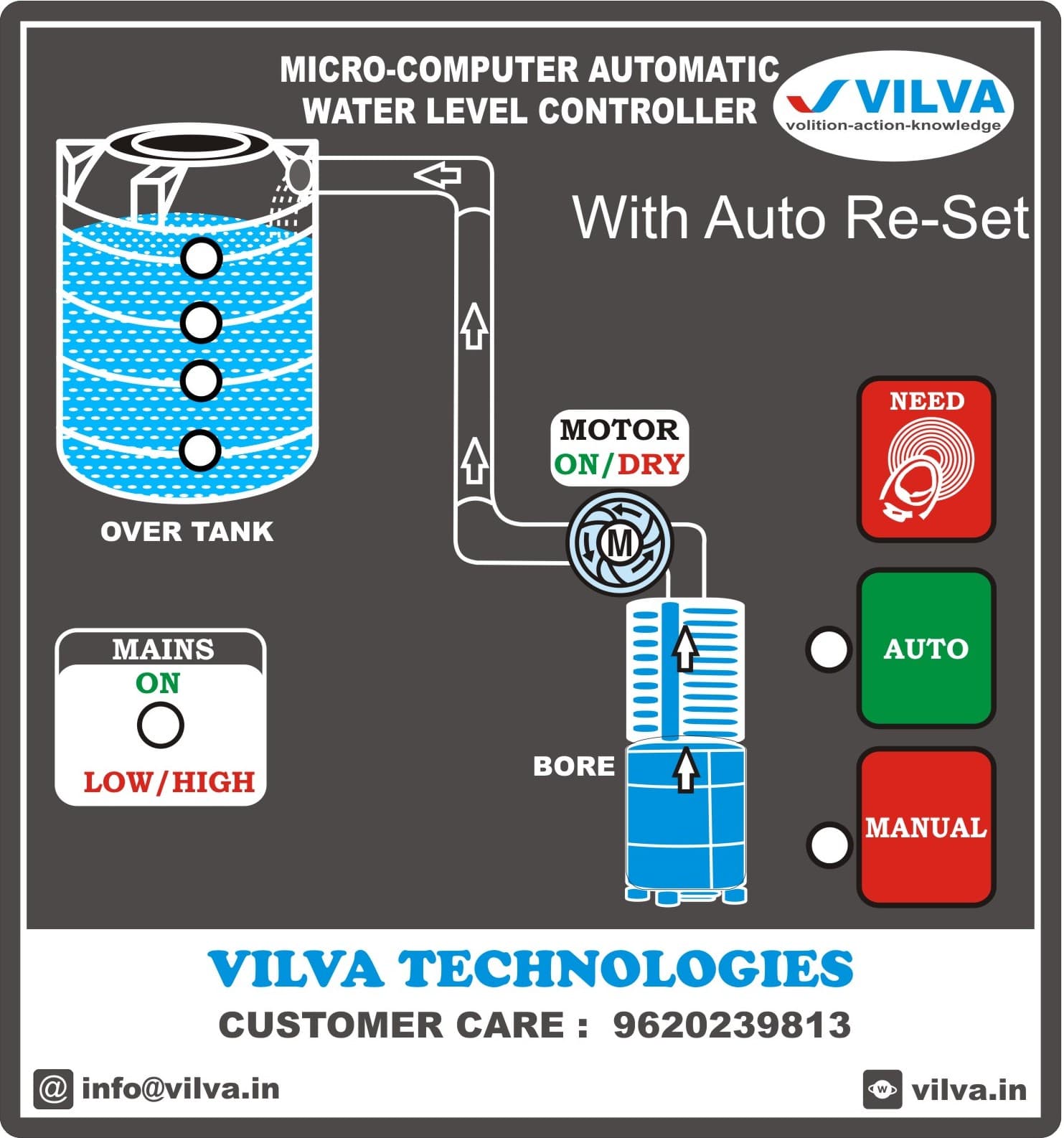
Water Management Control System: Features Overhead tank level 25%, 50% 75% and 100% Water flow indications DRYRUN indication. Power supply indication Low/Hi voltage indication AUTO and MANUAL mode indications NEED option in auto mode Stainless steel bullet and flow guard sensors. Water Management Control System: Functional Specification This document establishes the official operational logic, automation parameters, and safety protocols for the embedded controller of the dual-tank fluid management system. ________________________________________ 1. Electrical Safety & Operational Safeguards • Voltage Monitoring: The microcontroller continuously samples the incoming voltage level. • Interlock Protocol: If the system detects a Low-Voltage or High-Voltage fault condition, the bore motor drive relay is strictly inhibited from initializing. • Fault Override: Voltage safety limits supersede all water-level demand cues. ________________________________________ 2. Autonomous Mode Operations (AUTO) 2.1 Replenishment Initiation • Demand Threshold: Initiation sequence executes when the overhead tank level drops to ≤ 25%. 2.2 Fluid Dynamics & Priming Diagnostics • Flow Detection Window: Upon motor activation, the system initiates a 3-minute priming countdown timer. • Positive Feedback Loop: If fluid flow is detected at the overhead tank inlet within 3 minutes, the Water Flow fascia indicator activates, and the pump maintains continuous operation. • Dry-Run Exception: If no fluid entry is registered within 3 minutes, the system cuts motor power, suppresses the flow indicator, and logs a DRYRUN fault state on the user interface. 2.3 Fault Recovery & Lockout Parameters • Transient Fault Reset: Upon an initial DRYRUN event, the controller enters a 1-hour cooling period. After 1 hour, the system executes an Auto-Reset routine and attempts replenishment. • Critical Lockout: If a DRYRUN event registers more than 2 consecutive times, the system transitions into a Permanent Fault State. • Manual Override Clearance: The Permanent Fault State completely disables the Auto-Reset routine. Normal system operations can only be restored via physical operator intervention by depressing the tactile NEED button. • Upper Limit Termination: When the overhead tank reaches 100% capacity, the motor is deactivated to prevent reservoir overflow. ________________________________________ 3. Operator Interface Commands & Manual Overrides 3.1 Semi-Automated Filling (NEED Routine) • Purpose: Allows operators to initiate a top-up sequence prior to reaching the low-level automation threshold. • Execution: Activated by a brief touch of the NEED button on the interface panel. • Safety Resets: The routine follows identical safety loops and terminates automatically when the overhead tank hits 100% or if a DRYRUN condition is encountered. 3.2 Auxiliary Manual Bypass (MANUAL Mode) • Purpose: Facilitates auxiliary direct water usage (e.g., ground cleaning, landscaping) by diverting the discharge line. • Execution: Activated via the MANUAL selection button. • Bypass Profile: The system forces the bore motor into continuous operation and bypasses the 3-minute dry-run flow timer restriction. • Termination & Auto-Reversion: The system automatically terminates Manual Mode and directly reverts to standard AUTO operation if: o The overhead tank sensor registers 100% capacity (Overfill safety protocol). o The operator manually engages the AUTO button on the control console.
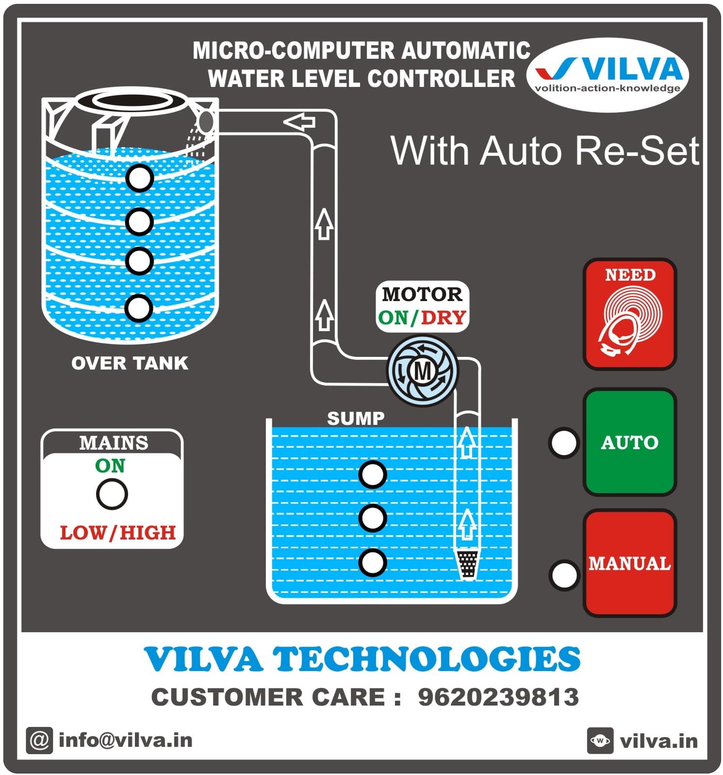
Water Management Control System: Features Overhead tank level 25%, 50% 75% and 100% Sump tank level 25%, 50% and 100%. Water flow indications DRYRUN indication. Power supply indication Low/Hi voltage indication AUTO and MANUAL mode indications NEED option in auto mode Stainless steel bullet and flow guard sensors. Water Management Control System: Functional Specification This document establishes the official operational logic, automation parameters, and safety protocols for the embedded controller of the dual-tank fluid management system. ________________________________________ 1. Electrical Safety & Operational Safeguards • Voltage Monitoring: The microcontroller continuously samples the incoming voltage level. • Interlock Protocol: If the system detects a Low-Voltage or High-Voltage fault condition, the sump motor drive relay is strictly inhibited from initializing. • Fault Override: Voltage safety limits supersede all water-level demand cues. ________________________________________ 2. Autonomous Mode Operations (AUTO) 2.1 Replenishment Initiation • Demand Threshold: Initiation sequence executes when the overhead tank level drops to ≤ 25%. • Source Verification: The system queries the sump tank level prior to motor engagement. • Engagement Window: If the sump reservoir level is ≥ 25%, the controller activates the sump motor relay and illuminates the Motor ON fascia indicator. 2.2 Fluid Dynamics & Priming Diagnostics • Flow Detection Window: Upon motor activation, the system initiates a 3-minute priming countdown timer. • Positive Feedback Loop: If fluid flow is detected at the overhead tank inlet within 3 minutes, the Water Flow fascia indicator activates, and the pump maintains continuous operation. • Dry-Run Exception: If no fluid entry is registered within 3 minutes, the system cuts motor power, suppresses the flow indicator, and logs a DRYRUN fault state on the user interface. 2.3 Fault Recovery & Lockout Parameters • Transient Fault Reset: Upon an initial DRYRUN event, the controller enters a 1-hour cooling period. After 1 hour, the system executes an Auto-Reset routine and attempts replenishment. • Critical Lockout: If a DRYRUN event registers more than 2 consecutive times, the system transitions into a Permanent Fault State. • Manual Override Clearance: The Permanent Fault State completely disables the Auto-Reset routine. Normal system operations can only be restored via physical operator intervention by depressing the tactile NEED button. 2.4 Resource Depletion & Recovery Thresholds • Low-Source Cut-off: If the source sump level drops below 25%, the motor is immediately deactivated to prevent mechanical damage. • Hysteresis Recovery: Following a low-source shutdown, the system ignores initial refills at 25% and enforces a buffer delay. Motor re-engagement is restricted until the sump volume recovers to a minimum threshold of 50%. • Upper Limit Termination: When the overhead tank reaches 100% capacity, the motor is deactivated to prevent reservoir overflow. ________________________________________ 3. Operator Interface Commands & Manual Overrides 3.1 Semi-Automated Filling (NEED Routine) • Purpose: Allows operators to initiate a top-up sequence prior to reaching the low-level automation threshold. • Execution: Activated by a brief touch of the NEED button on the interface panel. • Safety Resets: The routine follows identical safety loops and terminates automatically when the overhead tank hits 100% or if a DRYRUN condition is encountered. 3.2 Auxiliary Manual Bypass (MANUAL Mode) • Purpose: Facilitates auxiliary direct water usage (e.g., ground cleaning, landscaping) by diverting the discharge line. • Execution: Activated via the MANUAL selection button. • Bypass Profile: The system forces the sump motor into continuous operation and bypasses the 3-minute dry-run flow timer restriction. • Termination & Auto-Reversion: The system automatically terminates Manual Mode and directly reverts to standard AUTO operation if: o The overhead tank sensor registers 100% capacity (Overfill safety protocol). o The operator manually engages the AUTO button on the control console.